Was ist das MateLight?
Das MateLight ist eine interaktive LED-Installation. Es besteht aus RGB-LEDs und Club-Mate-Kästen. Damit ergibt sich ein Raster mit bunten Punkten. Also quasi ein Display.
Das MateLight ist klassischer Nerd-Shit. Es erfüllt keinen wirklich sinnvollen Zweck und wurde geschaffen, weil man es kann. Aber für ein paar Dinge kann man es schon verwenden. Es kann z.B. hervoragend als Effektbeleuchtung bei Veranstaltungen eingesetzt werden. Außerdem ist es ein tolles Spielzeug für Programmier-Padawane. Man jage ein paar Zahlen hinein und betrachte die bunt blinkende Welt.
Wo kann ich das MateLight sehen?
Auf der MakerFaire in Hannover
Oder an jedem Coding-Donnerstag im Maker Space
Made at code for Heilbronn</h2>
Das MateLight wurde von den Teilnehmern der Coding-Abende bei CodeFor Heilbronn entwickelt und hergestellt.
Contributors
img/contributors/theVale98.jpg
- TheVale98
- Hardware
img/contributors/LeoDJ.jpg
- LeoDJ
- Hardware, Software
img/contributors/Franz.jpg
- Franz
- Hardware
‘img/contributors/harmoniemand.jpg
- Jonathan
- Software
Wie kann ich helfen?
Hilfe können wir immer brauchen um neue Kästen zu bauen. Dazu sollte man löten können. Wir treffen und immer Donnerstags. Zwar wird nicht immer und ausschließlich am MateLight gearbeitet, aber immer öfter.
Außerdem kann das MateLight um coole neue Funktionen erweitert werden. Seien es Spiele oder der geplante Webservice. Dazu sollte man NodeJS oder Arduino (C++) programmieren können.
Software Documentation
API Documentation
The Matelight “API” is written in nodeJS and can be used in other scripts.
Scripts
Some scripts have already been created. They are located at Raspberry_Pi/materix_API/api/scripts.
- fromBitmap.js
- Takes a bitmap and displays it on the Matelight
- testScroll.js
- Displays a scrolling text on the Matelight
- glediatorBridge.js
- Takes ArtNet packages and displays them on the matelight
- Every crate row is one ArtNet universe. The channels start in the top left and travel down line wise
- This mapping has to be set up in gLEDiator, or any other ArtNet sender
Examples of how to launch the scripts can be found in the scripts README.
Future plans
- PixelFlut API
- HTTP API
- Create one central API that runs all the time and accepts input from multiple scripts
Hardware Documentation
Topology
The centerpiece of the installation is a Raspberry Pi with a USB to Serial adapter and a 12V server power supply.
We didn’t use the hardware serial of the Rapsberry Pi directly, because we already destroyed a Raspberry Pi by inducing voltage spikes or something like that.
XLR pinout
The serial TX and 12V from the power supply get connected to the pins of a XLR plug like this:
- +12V
- GND
- Serial Data
This plug is then connected to the first crate.
We also made some intermediary cables to feed the power to multiple points in the matrix to reduce the current flowing through the XLR plugs.
These were built just like normal pass-through cables, but with an extra XLR plug added for injecting 12V.
Building a crate
Materials needed
| Amount | Article | Approx. Price | Links |
|---|---|---|---|
| 1 | Club Mate Crate | 4.50€ | |
| 1 | Arduino Pro Mini 5V | 1.50€ | AliExpress |
| 20/50 LEDs | 12mm WS2811 LED String | 5€ | AliExpress |
| 1 | LM2596S Step Down | 1€ | eBay |
| 1 | XLR panel mount jack male | 2€ | eBay |
| 1 | XLR panel mount jack female | 2€ | eBay |
| 1 | XLR microphone cable 0.5m | 3€ | eBay |
| 24/40 pins | Female header | 0.10€ | AliExpress |
| Some | Plywood | ||
| Some | Cardboard |
Instructions
- Clean out all bottles
- Wrap the bottles in aluminum foil and secure it with tape
- Put a LED into each bottle following this pattern:
(seen from back, ↥ top ↥) ╔═══════════════════════════╗ ║ ○ → ○ ○ → ○ ○ ║ →{out} ║ ↑ ↓ ↑ ↓ ↑ ║ ║ ○ ○ ○ ○ ○ ║ ║ ↑ ↓ ↑ ↓ ↑ ║ ║ ○ ○ ○ ○ ○ ║ ║ ↑ ↓ ↑ ↓ ↑ ║ {in} → ║ ○ ○ → ○ ○ → ○ ║ ╚═══════════════════════════╝ (↧ bottom ↧) - Solder female headers for the Arduino to a piece of prototyping board
- Build the wooden back plate (schematics coming soon)
- Drill holes and screw the XLR Sockets in (male left, female right)
- Glue the buck converter and prototyping board from the inside to the wood
- Follow the wiring steps
- Put cardboard padding between the bottles and the wood plate
- Screw the wood plate onto the crate
- Flash the firmware onto the Arduino
- chose the correct firmware from Crate_Arduino_Receiver by the amount of bottles in a crate
- Connect all crates together with XLR cables in a serpentine pattern like this:
             (back side of array)
       [ ] → [ ] → [ ] → [ ] → [ ] → [ ] → [ ]
        ↑
       [ ] ← [ ] ← [ ] ← [ ] ← [ ] ← [ ] ← [ ]   (<- this row of crates is flipped 180°)
                                            ↑
{in} → [ ] → [ ] → [ ] → [ ] → [ ] → [ ] → [ ]
Wiring Instructions Step by Step
Start with the following plywood plate:
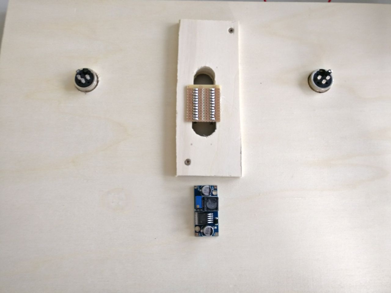
Step 1
Connect the 12V power passthrough cable
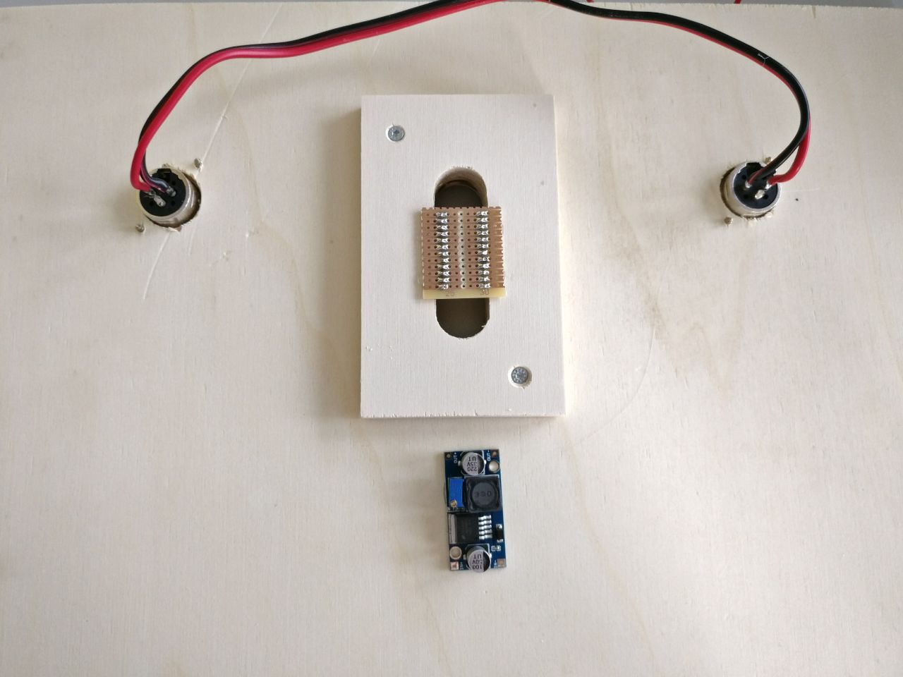
Step 2
Connect the 12V power from the XLR input
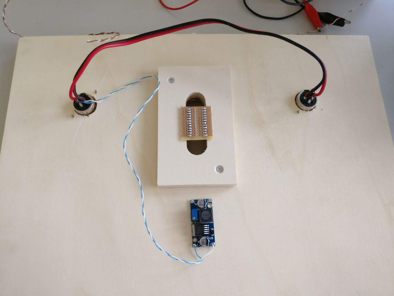
Step 3
Connect the regulated 5V to the Arduino 5V/VCC pin
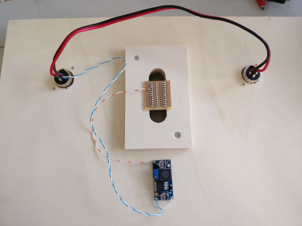
Step 4
Connect XLR data in and GND to Arduino RX and GND pins
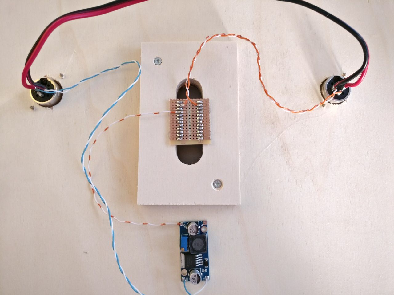
Step 5
Connect the Arduino TX pin to XLR data out
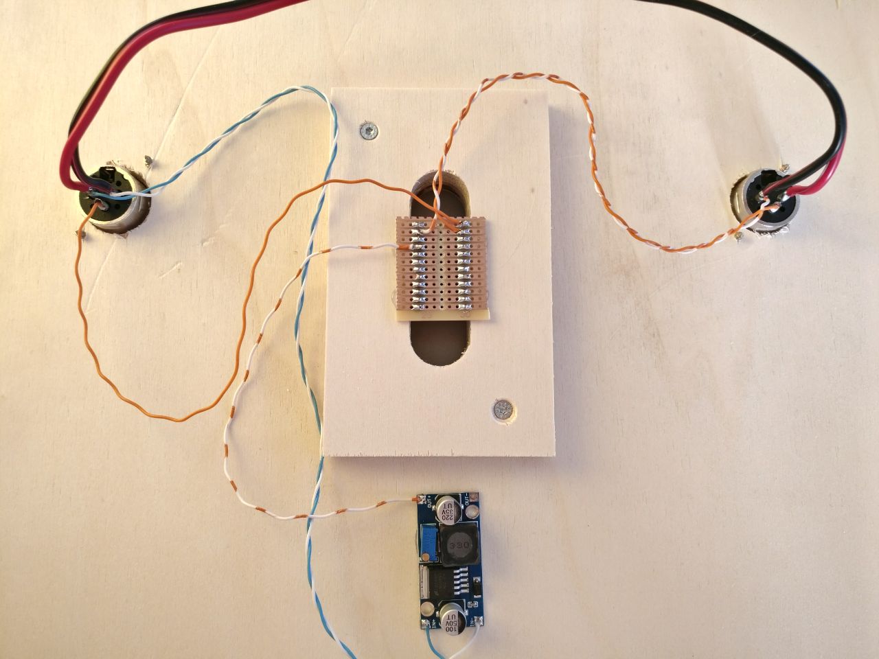
Step 6
Connect the 5V power wires for the LEDs to the buck converter
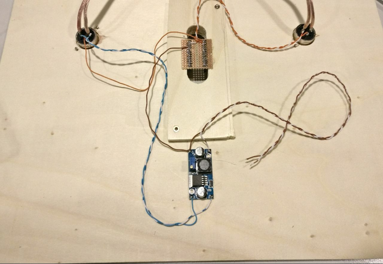
Step 7
Connect the LED data wire to Arduino pin 2
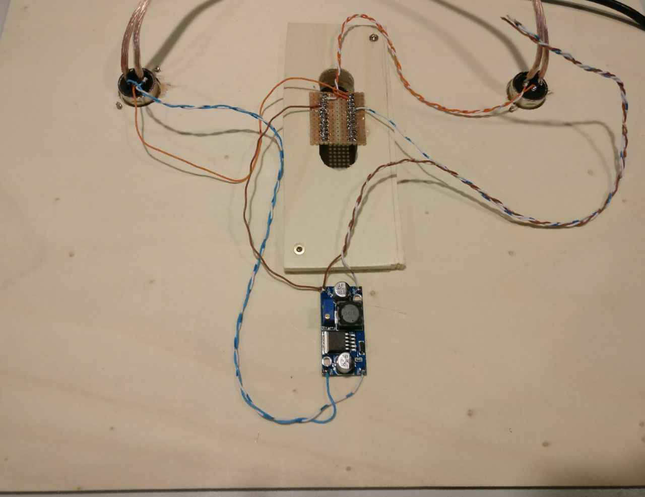
Step 8
Connect the three open cables from step 7 to the input of LED string accordingly
